Vapor chamber or heat pipe — which problem are you solving?
Both move heat by phase change, but they solve different problems. Start by deciding whether spreading or transport is your bottleneck.
“Is a vapor chamber better than a heat pipe?” has no answer, because the two components address different problems.
Classify the problem first
Thermal problems come in roughly two kinds.
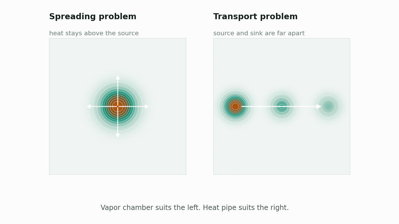
Spreading problems — heat must move from a small source across a large surface, but spreading resistance keeps everything but the area directly above the source cold. You have plenty of dissipation area and only part of it is working.
Transport problems — the heat source and the dissipation surface are physically separated, and heat has to travel from A to B.
Vapor chambers are good at spreading; heat pipes are good at transport. Their geometry says so: a vapor chamber is a wide flat two-dimensional structure, a heat pipe is a long thin one-dimensional one.
How to tell if you have a spreading problem
There is a quick test. Take an IR image of the heat sink surface.
- Hot directly above the source, cold at the edges → spreading resistance dominates. A vapor chamber or high-conductivity spreader will help.
- Uniformly warm across the sink → spreading is already adequate. Look at convection or dissipation area instead.
In simulation, break out spreading resistance as its own term and check its share of the total.

Spreading resistance is governed by the spreader’s conductivity and the area it spreads over. This is the regime where raising effective conductivity beats adding area.
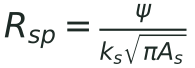
Above 30% of the total, improving spreading pays well.
Selection criteria
| Condition | Vapor chamber | Heat pipe |
|---|---|---|
| Source-to-sink distance | Short (same plane) | Long (50mm+) |
| Direction needed | 2D spreading | 1D transport |
| Thickness constraint | 0.3mm and up | 2mm round / 0.6mm flattened |
| Shape freedom | Mostly planar, hard to bend | Bends and forms easily |
| Unit cost | Higher | Lower |
| Manufacturing difficulty | High (vacuum and charge control) | Comparatively low |
| Orientation sensitivity | Relatively tolerant | Depends on wick structure |
Mistakes we see often
1. Adding more heat pipes to a spreading problem
Three pipes over the heat source still leave the regions between them poorly served. Placing a spreading layer underneath frequently beats adding pipe count.
2. Ruling out vapor chambers on thickness alone
0.35mm-class vapor chambers are in volume production. But as thickness drops, wick options narrow and Q-max falls steeply — calculate the heat you actually need to move before ruling either way.
3. Not considering the combination
Spreading with a vapor chamber over the source, then transporting to a remote sink with heat pipes, is often the most efficient arrangement. In laptops this is already standard practice.
4. Not checking Q-max in the real orientation
Datasheet Q-max is usually horizontal or gravity-assisted. Maximum transport is set by the wick’s capillary pressure minus the gravity term, so orientation changes the answer.

The second term inside the bracket is the one that grows with tilt angle θ. If your product is used upright or tilted, get the number for that orientation. Depending on wick structure the difference can exceed 30%.
Summary
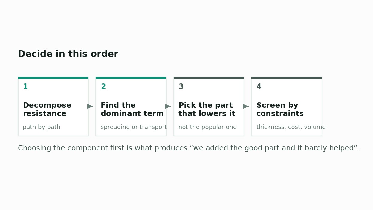
Don’t pick the component and then fit the problem to it. The order is the reverse:
- Decompose thermal resistance path by path
- Determine whether spreading or transport dominates
- Choose the component that reduces that term
- Narrow candidates by thickness, cost, and manufacturability
Following that order avoids most instances of “we added the good part and it barely helped.”
If you need help deciding, get in touch. We start by decomposing the resistance of your current design.